Rollicking Tracks II
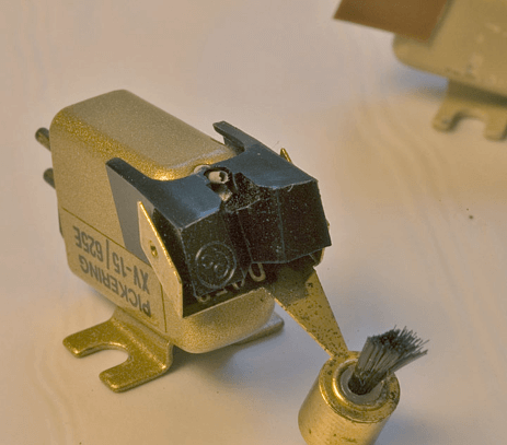
Let’s consider a work of a tonearm, starting from the installation of the needle into the groove. The needle being in a spiral groove starts to move gradually toward the center of the record. The tonearm, due to the rest mass remains fixed until the groove through the needle, and the elastic element of cantilever suspension, creates inside the latter the starting force of the tonearm, which is 3-4 times higher than the force required for uniform motion. The tonearm under the influence of this force starts to move towards the center of the record. But, because of stored in the elastic energy that exceeds the needed one to maintain uniform motion, the tonearm extends its neutral position and stops only when the compression force in the elastic element reaches the value of strength that stops it. The tonearm stops and the process starts over again. This job description is suitable for ideal conditions. But it’s not our case. All records are are eccentric and warped. And tonearm should accelerate and brake while performing every turnover. The elastic element of the cantilever is deformed from the left side, then from the right side, coils (magnet) of the cantilever deviate the optimal position, generated EMF becomes not symmetrical at the left side and then at the right side, that causes start of sound distortion. In the 60s, knowing about this problem, small brushes were invented, which were founded on the head (behind a needle or on its side) and pulled the tonearm instead of a cantilever elastic element (many people thought that the brush was needed to clean the groove).
But the bristles, placed in a modulated groove, started to shiver (and there was a lot of bristles), the tremor passed on the head body and contributed to deteriorate the sound. The bristles were not established.
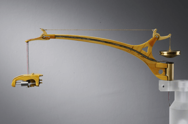
 A little more about the modulated groove. Or rather on the friction force of the needle on the groove walls. This force is taken into account while calculation of the required effort of the anti-skating system (friction force multiplied by the leverage action of this force, gives torque, from which, by reducing the force of the leverage to the point of force application of thread or spring anti-skating system, we receive the desired spring force or weight of the load). But all this is true for non-modulated groove. In the modulated sound groove impacts load effect the needle (Overload 1000 G) and in such a case there is nothing to talk about the anti-skating. Unfortunately we can not show the video about the behavior of the head, hung out on flexible filaments. In a nutshell what we have seen.
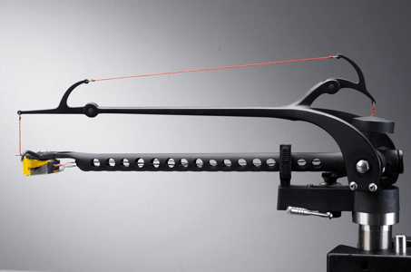
The head and its suspension system with two tungsten counterweights, with a total weight of about 35 grams, twitches its modulated groove forward and backward and rotating around the needle to the right and to the left at to an angle of plus — minus 30 degrees.
Try to perform the following experiment. Late at night when it is quiet in the house, turn on only the player and put the needle on a rotating record. In majority cases, you will hear a rather loud sound coming from a head and tonearm together. Now you can imagine how much powerful is oscillation of the sound groove that is coming out to «sound» shaking of the head and tonearm. Just do not think at once of the opposite — of the head body and of the tonearm tube made of rubber. And you need the following. So, try the following. Between the head and the tonearm apron install three small plasticine balls with a diameter of 0.2 — 0.3 mm. Or try such a laminated shim. And replace the machine metal screws with the plastic ones. Because of such reworks the tonearm leg has to be raised.
An illustrative example. Tonearm is a brass musical instrument: head holder is a mouthpiece, tonearm body is a body of flute, hoboy, saxophone. Head «blows» the sounds into a trumpet. The trumpet (resonator) enhances them. And…transfers (returns) with a delay to the head body. Phase and intermodulation do not improve. And if from the other side a powerful RUMBLE makes its way to the tonearm trumpet, so the ambiance becomes not joyful at all. The trumpet with holes, or «U» shaped cross-sectional tonearm cardinally improves the situation.
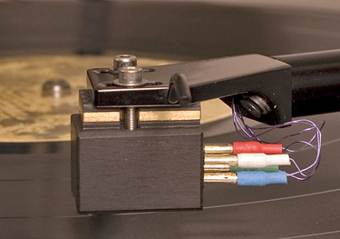
Wires inside tonearm is taboo. In the best case the brand of wire and connectors is indicated. Some interesting figures. The ratio of cross-sectional area of the coil wire in the head to the cross-sectional area of the inside tonearm wire of CARDAS 1:55, from VDH 1:75. Resistance of copper is less than the resistance of tin in 15 times, and with relation to solder — in 35 times. So every extra soldering, especially with the low-power signal, making its negative (what can be else?) contribution, like nigger in the woodpile, to the audio signal. And now let’s try to list the number of connections in the signal path from the connector head to the entrance to the equalizer or step-up transformer: outlet on the pin of the head, short wire solder, solder to pin outlet of headshell, outlet of headshell, pin outlet of headshell(inside tonearm), soldering of inside tonearm wire, soldering to pin outlet in the tonearm leg, soldering to the pin outlet, interconnect wire, soldering to the pin outlet of the interconnect wire, interconnect outlet (and there are tonearms with removable trumpet — plus one more outlet). But there is a way out, it is possible to lay a wire from the pin of the head (connecting wire to pin using silicone tube) to the pin of interconnect outlet! Extremals can try to make a connection with only two inside tonearm wires dividing conductors inside the wire in half (because each conductor within such wires is coated with a layer of varnish, so-called litz).
Therethrough, reducing the ratio of cross section area between the wire coil and inside tonearm wiring. It is desirable to set inside the tonearm the beads made of insulating material with four (two) holes through which to stretch the inside tonearm wires. Read next time about headshell and rotation nodes…
![]()
Aleksey Oksanenko